The Huawei S6730-S24X6Q is a high-performance Ethernet switch designed to meet the demands of modern data centers and campus networks. It offers advanced features and robust specifications to ensure efficient and reliable network operations.
Key Features
▪ High Port Density: 24 x 10 Gigabit SFP+ ports and 6 x 40 Gigabit QSFP+ ports.
▪ High Switching Capacity: Up to 2.4 Tbit/s to handle heavy traffic loads.
▪ Advanced Layer 2 and Layer 3 Features: Supports comprehensive protocols for versatile network configurations.
▪ Stacking Capability: Supports stacking through 10GE SFP+ and 40GE QSFP+ ports for simplified management.
▪ Energy Efficiency: Designed for low power consumption to reduce operational costs.
▪ Comprehensive Security: Offers features like ACLs, 802.1X authentication, and DHCP snooping for enhanced network protection.
▪ Quality of Service (QoS): Provides traffic classification and prioritization to ensure optimal performance for critical applications.
▪ Flexible Management: Supports various management methods, including CLI, web-based management, and SNMP.
▪ High Reliability: Features redundant power supplies and hot-swappable fan modules for continuous operation.
▪ Virtual Extensible LAN (VXLAN): Supports VXLAN L2 and L3 gateways for network virtualization.
Technical Specifications
Ports: 24 x 10GE SFP+ ports, 6 x 40GE QSFP+ ports.
Switching Capacity: 2.4 Tbit/s.
Forwarding Performance: 480 Mpps.
Dimensions (H x W x D): 43.6 mm x 442.0 mm x 420.0 mm (1.72 in. x 17.4 in. x 16.5 in.).
Weight (with packaging): 8.9 kg (19.62 lb).
Power Supply: Supports dual AC and DC power modules.
Operating Temperature: -5°C to +45°C (23°F to 113°F) at an altitude of 0-1800 m (0-5906 ft.).
Operating Humidity: 5% to 95%, noncondensing.
Stacking Support: Up to 16 physical ports for stacking using 10GE SFP+ and 40GE QSFP+ ports.
Airflow Direction: Air intake from front, air exhaustion from rear (front-to-rear).
Port Details
10GE SFP+ Ports: 24 ports supporting various optical modules and cables, including GE optical modules, 10GE SFP+ optical modules, and high-speed copper cables.
40GE QSFP+ Ports: 6 ports compatible with QSFP+ optical modules and high-speed copper cables. Note: A QSFP+ optical port cannot be split into four 10GE ports.
Power and Cooling
The S6730-S24X6Q supports dual hot-swappable power modules, allowing for AC and DC inputs:
AC Input: 100 V AC to 240 V AC, 50/60 Hz.
High-Voltage DC Input: 240 V DC.
DC Input: -48 V DC to -60 V DC.
Maximum Power Consumption: 249 W.
Typical Power Consumption: 135 W.
Fan Modules: Four pluggable fan modules with front-to-rear airflow design for efficient cooling.
Stacking and Virtualization
The switch supports stacking through its 10GE SFP+ and 40GE QSFP+ ports, allowing multiple switches to function as a single logical unit for simplified management and enhanced scalability. It also supports VXLAN L2 and L3 gateways, enabling network virtualization for flexible and efficient network designs.
Security Features
The S6730-S24X6Q offers comprehensive security features to protect network integrity:
Access Control Lists (ACLs): Permit or deny traffic based on predefined security policies.
802.1X Authentication: Ensures that only authorized users can access the network.
DHCP Snooping: Prevents unauthorized DHCP servers from distributing IP addresses.
IP Source Guard: Blocks packets with spoofed IP addresses.
Dynamic ARP Inspection (DAI): Protects against ARP spoofing attacks.
Quality of Service (QoS)
The switch provides advanced QoS features to ensure optimal performance for critical applications:
Traffic Classification: Identifies and classifies incoming traffic based on various parameters.
Traffic Policing and Shaping: Controls the rate of traffic sent or received on a network interface.
Priority Queuing: Ensures that high-priority traffic is transmitted first.
Congestion Management: Implements mechanisms to prevent and manage network congestion.
Management and Maintenance
The S6730-S24X6Q supports various management methods for ease of use:
Command-Line Interface (CLI): Provides a text-based interface for configuration and monitoring.
Web-Based Management: Offers a graphical user interface accessible through web browsers.
Huawei CloudEngine S6730-S24X6Q Switches
Huawei All Series Switches New and Used
For Cisco product list and quote, please visit: https://www.hi-network.com/categories/cisco or contact us at www.hi-network.com (Email: [email protected])
S6730-S24X6Q (02353AJW/02353AJW-001/02353AJW-003/02353AJW-004)
Version Mapping
Table 4-227 lists the mapping between the S6730-S24X6Q chassis and software versions.
Table 4-227 Version mapping
| Series | Model | Software Version |
|---|---|---|
| S6730-S | S6730-S24X6Q | 02353AJW: V200R019C00 and later versions02353AJW-001: V200R020C10 and later versions02353AJW-003: V200R021C10SPC500 and later versions (If V200R021C00SPC100 is used, install V200R021SPH011 or a later patch.)02353AJW-004: V200R021C10SPC600 and later versions (If V200R021C00SPC100 is used, install V200R021SPH013 or a later patch.)NOTE:V200R021C01 is not supported.Some models cannot be downgraded due to component upgrade. Therefore, you are advised to run the display system-software information command (supported in V200R021C00 and later versions) to check the software versions supported by the device before performing a downgrade. |
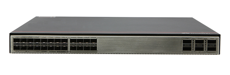
Appearance and Structure
Figure 4-94 S6730-S24X6Q appearance

| 1 | Twenty-four 10GE SFP+ portsApplicable modules and cables:GE optical moduleGE-CWDM optical moduleGE-DWDM optical moduleGE copper module10GE SFP+ optical module (OSXD22N00 not supported)10GE SFP+ Copper Modules (supported in V200R023C10 and later versions)10GE-CWDM optical module10GE-DWDM optical module1 m, 3 m, 5 m, and 10 m SFP+ high-speed copper cables3 m and 10 m SFP+ AOC cables0.5 m and 1.5 m SFP+ dedicated stack cables (supported by the last 16 SFP+ ports and used only for zero-configuration stacking) | 2 | Six 40GE QSFP+ optical portsApplicable modules and cables:QSFP+ optical module1 m, 3 m, and 5 m QSFP+ to QSFP+ high-speed copper cables10 m QSFP+ to QSFP+ AOC cable2 m QSFP28 dedicated stack cable (supported in V200R020C10 and later versions)QSFP28 optical module (supported in V200R024C00 and later versions, need a license loaded)1 m QSFP28 to QSFP28 high-speed copper cable (supported in V200R024C00 and later versions, need a license loaded)10 m QSFP28 to QSFP28 AOC cable (supported in V200R024C00 and later versions, need a license loaded)NOTE:A QSFP+ optical port cannot be split into four 10GE ports.In V200R024C00 and later versions, a RTU license can be loaded to increase the port rate to 100 Gbit/s.The QSFP+ ports can work as 100GE ports after you activate the license, run the assign port-type 100ge [ slot slot-id | all ] command, and restart the switch. |
| 3 | Ground screwNOTE:It is used with a ground cable. | 4 | SSD card slotNOTE:This slot is reserved for future use. |
| 5 | One console port | 6 | One ETH management port |
| 7 | One USB port | 8 | One PNP buttonNOTICE:To restore the factory settings and reset the switch, hold down the button for at least 6 seconds.To reset the switch, press the button.Resetting the switch will cause service interruption. Exercise caution when you press the PNP button. |
| 9 | Fan module slot 1NOTE:Applicable fan module: FAN-031A-B (Fan Box (B, Fan Panel Side Exhaust)) | 10 | Fan module slot 2NOTE:Applicable fan module: FAN-031A-B (Fan Box (B, Fan Panel Side Exhaust)) |
| 11 | Fan module slot 3NOTE:Applicable fan module: FAN-031A-B (Fan Box (B, Fan Panel Side Exhaust)) | 12 | Fan module slot 4NOTE:Applicable fan module: FAN-031A-B (Fan Box (B, Fan Panel Side Exhaust)) |
| 13 | Power module slot 1NOTE:Applicable power module:PAC600S12-CB (600 W AC&240 V DC Power Module)PAC600S12-EB (600 W AC&240 V DC Power Module)PAC600S12-DB (600 W AC&240 V DC Power Module) (applicable in V200R020C10 and later versions)PDC1000S12-DB (1000 W DC Power Module) | 14 | Power module slot 2NOTE:Applicable power module:PAC600S12-CB (600 W AC&240 V DC Power Module)PAC600S12-EB (600 W AC&240 V DC Power Module)PAC600S12-DB (600 W AC&240 V DC Power Module) (applicable in V200R020C10 and later versions)PDC1000S12-DB (1000 W DC Power Module) |
Port Description
10GE SFP+ optical port
A 10GE SFP+ Ethernet optical port supports auto-sensing to 1000 Mbit/s. It sends and receives service data at 1000 Mbit/s or 10 Gbit/s. Table 4-228 describes the attributes of a 10GE SFP+ Ethernet optical port.
Table 4-228 Attributes of a 10GE SFP+ port
| Attribute | Description |
|---|---|
| Connector type | LC/PC |
| Optical port attributes | Depend on the optical module used |
| Standards compliance | IEEE802.3ae |
| Working mode | GE/10GE auto-sensing |
40GE QSFP+ optical port
A 40GE QSFP+ optical port sends and receives service traffic at 40 Gbit/s. Table 4-229 describes the attributes of a QSFP+ optical port.
Table 4-229 Attributes of a QSFP+ optical port
| Attribute | Description |
|---|---|
| Connector type | MPO/LC |
| Optical port attributes | Depend on the optical module used |
| Standards compliance | IEEE802.3ba |
Console port
The console port is connected to a console for on-site configuration. The port must use a console cable. The console port is used when a switch is powered on for the first time. For details about the attributes of a console port, see Table 4-230.
Table 4-230 Attributes of a console port
| Attribute | Description |
|---|---|
| Connector type | RJ45 |
| Standards compliance | RS-232 |
| Working mode | Duplex Universal Asynchronous Receiver/Transmitter (UART) |
| Baud rate | 9600 bit/s, 19200 bit/s, 38400 bit/s, 57600 bit/s, or 115200 bit/sDefault value: 9600 bit/s |
ETH management port
You can connect a switch to a configuration terminal or network management workstation through the ETH management port to configure the switch locally or remotely. The port must use an Ethernet cable. You can choose to download the software package through the ETH management port in the BootLoad menu. File transfer through the ETH management port is faster than transfer through the console port. Table 4-231 describes the attributes of an ETH management port.
Table 4-231 Attributes of an ETH management port
| Attribute | Description |
|---|---|
| Connector type | RJ45 |
| Standards compliance | IEEE802.3 |
| Working Mode | 10/100 Mbit/s auto-sensing |
| Maximum transmission distance | 100 mIn V200R012C00 and later versions, you can log in to the switch that contains the ETH management port for the first time through the ETH port. For details, see "First Login to a Switch" in the Configuration Guide - Basic Configuration. |
USB port
The USB port can have a USB flash drive connected to upgrade the switch, or transfer configuration files or other files. The USB port can only connect to a USB flash drive that complies with USB 2.0.

USB flash drives from different vendors differ in model compatibility and drivers. If a USB flash drive cannot be used, try to replace it with another one from a mainstream vendor. Switches support a maximum of 128 GB USB flash drives.
Indicator Description
Figure 4-95 Indicators on the S6730-S24X6Q

Table 4-232 Description of indicators on the switch
| No. | Indicator | Name | Color | Status | Description |
|---|---|---|---|---|---|
| 1 | SYS | System status indicator | - | Off | The system is not running. |
| Green | Fast blinking | The system is starting. | |||
| Green | Steady on | During the system startup preparation phase, the SYS indicator is steady green, which lasts for a maximum of 30 seconds. | |||
| Green | Slow blinking | The system is running normally. | |||
| Red | Steady on | The system does not work normally after registration, or a fan alarm or a temperature alarm has been generated. | |||
| 2 | MST | Stack indicator | - | Off | The switch is not the master switch in a stack. |
| Green | Blinking | The switch is the master switch in a stack or a standalone switch. | |||
| 3 | ID | ID indicator | - | Off | The ID indicator is not used (default state). |
| Blue | Steady on | The indicator identifies the switch to maintain. The ID indicator can be turned on or off remotely to help field engineers find the switch to maintain. | |||
| 4 | - | Service port indicator (10GE optical port)NOTE:Each optical port has two single-color indicators. The one on the left is the ACT indicator (yellow), and the one on the right is the LINK indicator (green).Arrowheads show the positions of ports. A down arrowhead indicates a port at the bottom, and an up arrowhead indicates a port at the top. | - | Off | The port is not connected or has been shut down. |
| Green | Steady on | A link has been established on the port. | |||
| - | Off | The port is not sending or receiving data. | |||
| Yellow | Blinking | The port is sending or receiving data. | |||
| 5 | - | Service port indicator (40GE optical port)NOTE:Each optical port has one single-color indicator. Arrowheads show the positions of ports. | - | Off | The port is not connected or has been shut down. |
| Green | Steady on | A link has been established on the port. | |||
| Blinking | The port is sending or receiving data. | ||||
| 6 | L/A | ETH port indicator | - | Off | The ETH port is not connected. |
| Green | Steady on | The ETH port is connected. | |||
| Green | Blinking | The Eth port is sending or receiving data. | |||
| 7 | USB | USB-based deployment indicator | - | Off | No USB flash drive is connected to the switch.The USB port is damaged.The indicator is damaged.The USB flash drive does not have any configuration file and cannot be used for deployment.The switch has been upgraded using the USB flash drive and is restarting. |
| Green | Steady on | A USB-based deployment has been completed. | |||
| Green | Blinking | The system is reading data from a USB flash drive. | |||
| Yellow | Steady on | The switch has copied all the required files and completed the file check. The USB flash drive can be removed from the switch. | |||
| Red | Blinking | An error has occurred when the system is executing the configuration file or reading data from the USB flash drive. |
Power Supply Configuration
The switch can use a single power module or double power modules for 1+1 power redundancy. Pluggable AC and DC power modules can be used together in the same switch.
Heat Dissipation
The S6730-S24X6Q uses pluggable fan modules for forced air cooling. Air flows in from the front side and exhausts from the rear panel.

This figure only shows the airflow direction and does not depict the actual device.
Technical Specifications
Table 4-233 lists technical specifications of the S6730-S24X6Q.
Table 4-233 Technical specifications
| Item | Description |
|---|---|
| Memory (RAM) | 4 GB |
| Flash | 2 GB in total. To view the available flash memory size, run the display version command. |
| Mean time between failures (MTBF) | 62.27 years |
| Mean time to repair (MTTR) | 2 hours |
| Availability | > 0.99999 |
| Service port surge protection | N/A |
| Power supply surge protection | Using AC power modules: ±6 kV in differential mode, ±6 kV in common modeUsing DC power modules: ±2 kV in differential mode, ±4 kV in common mode |
| Dimensions (H x W x D) | Basic dimensions (excluding the parts protruding from the body): 43.6 mm x 442.0 mm x 420.0 mm (1.72 in. x 17.4 in. x 16.5 in.)Maximum dimensions (the depth is the distance from ports on the front panel to the handle on the rear panel): 43.6 mm x 442.0 mm x 446.0 mm (1.72 in. x 17.4 in. x 17.6 in.) |
| Weight (with packaging) | 8.9 kg (19.62 lb) |
| Stack ports | Any 10GE SFP+ ports (a maximum of 16 physical ports)Any 40GE QSFP+ ports (a maximum of 6 physical ports) |
| RTC | Supported |
| RPS | Not supported |
| PoE | Not supported |
| Rated voltage range | AC input: 100 V AC to 240 V AC, 50/60 HzHigh-Voltage DC input: 240 V DCDC input: -48 V DC to -60 V DC |
| Maximum voltage range | AC input: 90 V AC to 290 V AC, 45 Hz to 65 HzHigh-Voltage DC input: 190 V DC to 290 V DCDC input: -38.4 V DC to -72 V DC |
| Maximum power consumption | High temperature 45°C (113°F), 100% traffic, and dual power modules: 170 WHigh temperature 45°C (113°F), 100% traffic, long-distance optical module, 100% fan speed, and dual power modules: 249 W |
| Typical power consumption | 30% traffic under the ATIS standard and dual power modules: 135 W |
| Operating temperature | -5°C to +45°C (23°F to 113°F) at an altitude of 0-1800 m (0-5906 ft.)NOTE:When the altitude is 1800-5000 m (5906-16404 ft.), the highest operating temperature reduces by 1°C (1.8°F) every time the altitude increases by 220 m (722 ft.).The switch cannot be started when the ambient temperature is lower than 0°C (32°F). |
| Storage temperature | -40°C to +70°C (-40°F to +158°F) |
| Noise under normal temperature (27°C, sound power) | < 65 dB(A) |
| Relative humidity | 5% to 95%, noncondensing |
| Operating altitude | 0-5000 m (0-16404 ft.) |
| Certification | EMC certificationSafety certificationManufacturing certification |
| Part number | 02353AJW02353AJW-00102353AJW-00302353AJW-004 |