Introduction to Huawei S5731-H48P4XC
The Huawei S5731-H48P4XC is a high-performance, feature-rich switch designed to meet the evolving needs of modern enterprise networks. As part of Huawei's CloudEngine S5731-H series, this switch offers advanced capabilities to support high-bandwidth access and aggregation, making it an ideal choice for various networking scenarios.
Key Features
▪ High-Density Gigabit Access: Provides 48 Gigabit Ethernet ports for high-density access.
▪ Advanced Uplink Options: Equipped with 4 fixed 10GE SFP+ uplink ports for high-speed connections.
▪ Power over Ethernet (PoE+): Supports PoE+, delivering power to connected devices like IP phones and cameras.
▪ Scalability: Features an expansion slot for additional modules, enhancing flexibility.
▪ Stacking Capabilities: Supports stacking via 10GE SFP+ ports or rear card ports, simplifying network management.
Technical Specifications
▪ Dimensions: 43.6 mm x 442.0 mm x 420.0 mm (1.72 in. x 17.4 in. x 16.54 in.).
▪ Weight (with packaging): 8.8 kg (19.40 lb).
▪ Stack Ports: 10GE SFP+ ports on the front panel or ports on the rear card.
Deployment Scenarios
The S5731-H48P4XC is well-suited for various deployment scenarios, including:
▪ Enterprise Campus Networks: Provides high-density access for end-user devices in large campus environments.
▪ Data Center Access: Serves as an access switch in data centers, connecting servers and storage devices.
▪ Metropolitan Area Networks (MANs): Functions as an aggregation switch in MANs, consolidating traffic from access switches.
Conclusion
The Huawei S5731-H48P4XC switch combines high-density Gigabit access, advanced uplink options, PoE+ support, and scalability to meet the demands of modern enterprise networks. Its robust feature set and versatile deployment options make it a valuable asset for organizations seeking to enhance their network infrastructure.
Huawei CloudEngine Switch S5731-H48P4XC (02352SVD/-001/-003)
Huawei All Series Switches New and Used
For Huawei product list and quote, please visit: https://www.hi-network.com/categories/huawei or contact us at www.hi-network.com (Email: [email protected])
S5731-H48P4XC (02352SVD/02352SVD-001/02352SVD-003)
Version Mapping
Table 4-1499 lists the mapping between the S5731-H48P4XC chassis and software versions.
Table 4-1499 Version mapping
| Series | Model | Software Version |
|---|---|---|
| S5731-H | S5731-H48P4XC | 02352SVD: V200R013C02 and later versions02352SVD-001: V200R020C10 and later versions02352SVD-003: V200R021C10SPC600 and later versions (If V200R021C10SPC500 is used, install V200R021HP0121 or a later patch. If V200R021C00SPC100 is used, install V200R021SPH013 or a later patch.) |
Appearance and Structure
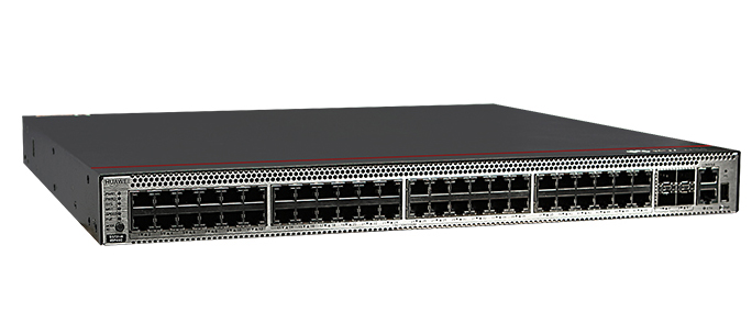
Figure 4-585 S5731-H48P4XC (02352SVD) appearance

Figure 4-586 S5731-H48P4XC (02352SVD-001/02352SVD-003) appearance

| 1 | Forty-eight PoE+ 10/100/1000BASE-T ports | 2 | Four 10GE SFP+ portsApplicable modules and cables:GE optical moduleGE-CWDM optical moduleGE-DWDM optical moduleGE copper module (100M/1000M auto-sensing)10GE SFP+ optical module (OSXD22N00 not supported)10GE-CWDM optical module10GE-DWDM optical modulePEN remote optical modules (V200R024C00 and later versions)1 m, 3 m, 5 m, and 10 m SFP+ high-speed copper cables3 m and 10 m SFP+ AOC cables0.5 m and 1.5 m SFP+ dedicated stack copper cables (used for zero-configuration stacking) |
| 3 | One console port | 4 | One ETH management port |
| 5 | One USB port | 6 | One PNP buttonNOTICE:To restore the factory settings and reset the switch, hold down the button for at least 6 seconds.To reset the switch, press the button.Resetting the switch will cause service interruption. Exercise caution when you press the PNP button. |
| 7 | Ground screwNOTE:It is used with a ground cable. | 8 | Rear card slotNOTE:Applicable card:ES5D21X08T00ES5D21Q02Q00S7X08000 (02312URW) (applicable in V200R019C10 and later versions)S7X08000 (02312URW-002) (applicable in V200R021C10SPC600 and later versions)S7Q02001 (02313UBW) (applicable in V200R021C01 and later versions)S7Q02001 (02313UBW-002) (applicable in V200R021C10SPC600 and later versions) |
| 9 | Fan module slot 1NOTE:Applicable fan module: FAN-023A-B (Fan Box (B, Fan Panel Side Exhaust)) | 10 | Fan module slot 2NOTE:Applicable fan module: FAN-023A-B (Fan Box (B, Fan Panel Side Exhaust)) |
| 11 | Power module slot 1NOTE:Applicable power module:PAC1000S56-CB (02312KND: 1000 W PoE AC&240 V DC Power Module)PAC1000S56-CB (02312KND-001: 1000 W PoE AC&240 V DC Power Module) (applicable in V200R019C10 and later versions)PAC1000S56-DB (1000 W PoE AC&240 V DC Power Module) (applicable in V200R020C10 and later versions)PDC1000S56-CB (1000 W PoE DC Power Module) (applicable in V200R021C00 and later versions)PAC600S56-CB (600 W PoE AC&240 V DC Power Module (Back to Front, Power panel side exhaust)) (applicable in V200R021C10 and later versions) | 12 | Power module slot 2NOTE:Applicable power module:PAC1000S56-CB (02312KND: 1000 W PoE AC&240 V DC Power Module)PAC1000S56-CB (02312KND-001: 1000 W PoE AC&240 V DC Power Module) (applicable in V200R019C10 and later versions)PAC1000S56-DB (1000 W PoE AC&240 V DC Power Module) (applicable in V200R020C10 and later versions)PDC1000S56-CB (1000 W PoE DC Power Module) (applicable in V200R021C00 and later versions)PAC600S56-CB (600 W PoE AC&240 V DC Power Module (Back to Front, Power panel side exhaust)) (applicable in V200R021C10 and later versions) |
Port Description
10/100/1000BASE-T port
A 10/100/1000BASE-T Ethernet electrical port sends and receives service data at 10/100/1000 Mbit/s, and must use an Ethernet cable. Table 4-1500 describes the attributes of a 10/100/1000BASE-T Ethernet electrical port.
Table 4-1500 Attributes of a 10/100/1000BASE-T Ethernet electrical port
| Attribute | Description |
|---|---|
| Connector type | RJ45 |
| Standards compliance | IEEE802.3, IEEE802.3u, IEEE802.3ab |
| Working mode | 10/100/1000 Mbit/s auto-sensing |
| Maximum transmission distance | 100 m |
10GE SFP+ optical port
A 10GE SFP+ Ethernet optical port supports auto-sensing to 1000 Mbit/s. It sends and receives service data at 1000 Mbit/s or 10 Gbit/s. Table 4-1501 describes the attributes of a 10GE SFP+ Ethernet optical port.
Table 4-1501 Attributes of a 10GE SFP+ port
| Attribute | Description |
|---|---|
| Connector type | LC/PC |
| Optical port attributes | Depend on the optical module used |
| Standards compliance | IEEE802.3ae |
| Working mode | GE/10GE auto-sensing |
Console port
The console port is connected to a console for on-site configuration. The port must use a console cable. The console port is used when a switch is powered on for the first time. For details about the attributes of a console port, see Table 4-1502.
Table 4-1502 Attributes of a console port
| Attribute | Description |
|---|---|
| Connector type | RJ45 |
| Standards compliance | RS-232 |
| Working mode | Duplex Universal Asynchronous Receiver/Transmitter (UART) |
| Baud rate | 9600 bit/s, 19200 bit/s, 38400 bit/s, 57600 bit/s, or 115200 bit/sDefault value: 9600 bit/s |
ETH management port
You can connect a switch to a configuration terminal or network management workstation through the ETH management port to configure the switch locally or remotely. The port must use an Ethernet cable. You can choose to download the software package through the ETH management port in the BootLoad menu. File transfer through the ETH management port is faster than transfer through the console port. Table 4-1503 describes the attributes of an ETH management port.
Table 4-1503 Attributes of an ETH management port
| Attribute | Description |
|---|---|
| Connector type | RJ45 |
| Standards compliance | IEEE802.3 |
| Working Mode | 10/100 Mbit/s auto-sensing |
| Maximum transmission distance | 100 mIn V200R012C00 and later versions, you can log in to the switch that contains the ETH management port for the first time through the ETH port. For details, see "First Login to a Switch" in the Configuration Guide - Basic Configuration. If you have logged in to the switch for the first time by pressing and holding the MODE button for 6 seconds or longer and saved the configuration, the default configuration on the ETH port will be cleared. In this case, you cannot log in to the switch for the first time through the ETH port. You are advised to log in to the switch for the first time through the ETH port. |
USB port
The USB port can have a USB flash drive connected to upgrade the switch, or transfer configuration files or other files. The USB port can only connect to a USB flash drive that complies with USB 2.0.
USB flash drives from different vendors differ in model compatibility and drivers. If a USB flash drive cannot be used, try to replace it with another one from a mainstream vendor. Switches support a maximum of 128 GB USB flash drives.
Indicator Description
Hold down the mode switch button for 6s and release it to start the web initial login mode. Either of the following situations will occur:
- If the switch has no configuration file, the system attempts to enter the web initial login mode. In this mode, the status of mode indicators is as follows:If the system enters the web initial login mode successfully, all mode indicators turn green and stay on for a maximum of 10 minutes.If the system fails to enter the initial login mode, all mode indicators fast blink for 10 seconds and then restore the default status.
- If the switch has a configuration file, the system cannot enter the web initial login mode. In this case, all mode indicators fast blink for 10s, and then return to the default states.
- Figure 4-587 Indicators on the S5731-H48P4XC (02352SVD)
- Figure 4-588 Indicators on the S5731-H48P4XC (02352SVD-001/02352SVD-003)
- Table 4-1504 Description of indicators on the switch


| No. | Indicator | Name | Color | Status | Description |
|---|---|---|---|---|---|
| 1 | PWR1 | Power module indicator | - | Off | No power module is available in power module slot 1, or the switch has only one power module but the power module does not work normally. |
| Green | Steady on | A power module is installed in power module slot 1 and is working normally. | |||
| Yellow | Steady on | The switch has two power modules installed. Any of the following situations occurs in power module slot 1:A power module is available in this slot but it is not connected to a power source.The power module in this slot has failed. | |||
| 2 | PWR2 | Power module indicator | - | Off | No power module is available in power module slot 2, or the switch has only one power module but the power module does not work normally. |
| Green | Steady on | A power module is installed in power module slot 2 and is working normally. | |||
| Yellow | Steady on | The switch has two power modules installed. Any of the following situations occurs in power module slot 2:A power module is available in this slot but it is not connected to a power source.The power module in this slot has failed. | |||
| 3 | SYS | System status indicator | - | Off | The system is not running. |
| Green | Fast blinking | The system is starting. | |||
| Green | Steady on | During the system startup preparation phase, the SYS indicator is steady green, which lasts for a maximum of 30 seconds. | |||
| Green | Slow blinking | The system is running normally. | |||
| Red | Steady on | The system does not work normally after registration, or a fan alarm or a temperature alarm has been generated. | |||
| 4 | MST | Stack indicator | - | Off | If you are not changing the indicator mode (default): The switch is a standby or slave switch in a stack or the stacking function is not enabled on the switch.If you are changing the indicator mode: The stack mode is not selected. |
| Green | Steady on | The stack mode is selected. The switch is a standby or slave switch in a stack, and the service port indicators show the stack ID of the switch. | |||
| Green | Blinking | If you are not changing the indicator mode (default): The switch is the master switch in a stack or a standalone switch with the stacking function enabled.If you are changing the indicator mode: The stack mode is selected. The switch is the master switch in a stack or a standalone switch, and the service port indicators show the stack ID of the master switch. After 45 seconds, the service port indicators automatically restore to the status mode. | |||
| 5 | SPEED | Speed indicator | - | Off | The speed mode is not selected. |
| Green | Steady on | The speed mode is selected, and service port indicators show the speed of each port. | |||
| 6 | PoE | PoE indicator | - | Off | The PoE mode is not selected. |
| Green | Steady on | The PoE mode is selected, and service port indicators show the PoE status of each port. | |||
| 7 | MODE | Mode switch button | - | - | When you press this button once, the service port indicators change to the stack mode and show the stack ID of the local switch.When you press this button a second time, the service port indicators change to the speed mode and show the speed of each service port.When you press this button a third time, the service port indicators change to the PoE mode and show the PoE status of each service port.When you press this button a fourth time, the service port indicators restore to the default mode and show the connection status and link activity of each service port.If you do not press the MODE button within 45 seconds, the service port indicators restore to the default mode. In this case, the SPEED and PoE indicators are off. |
| ID | ID indicatorNOTE:The mode switch button has an ID indicator. | - | Off | The ID indicator is not used (default state). | |
| Blue | Steady on | The indicator identifies the switch to maintain. The ID indicator can be turned on or off remotely to help field engineers find the switch to maintain. | |||
| 8 | - | Electrical service port indicator (one indicator for each port) | The indicator in the upper left corner of a port indicates the indicator of a port at the top, and the indicator in the upper right corner indicates the indicator of a port at the bottom. | Meanings of service port indicators vary in different modes. For details, see Table 4-1505 and Table 4-1506. | |
| Optical service port indicator (two indicators for each port) | Each optical port has two single-color indicators. The one on the left is the ACT indicator (yellow), and the one on the right is the LINK indicator (green).Arrowheads show the positions of ports. A down arrowhead indicates a port at the bottom, and an up arrowhead indicates a port at the top. | ||||
| 9 | ETH | ETH port indicator | - | Off | The ETH port is not connected. |
| Green | Steady on | The ETH port is connected. | |||
| Green | Blinking | The ETH port is sending or receiving data. | |||
| 10 | - | USB-based deployment indicator | - | Off | No USB flash drive is connected to the switch.The USB port is damaged.The indicator is damaged.The USB flash drive does not have any configuration file and cannot be used for deployment.The switch has been upgraded using the USB flash drive and is restarting. |
| Green | Steady on | A USB-based deployment has been completed. | |||
| Green | Blinking | The system is reading data from a USB flash drive. | |||
| Yellow | Steady on | The switch has copied all the required files and completed the file check. The USB flash drive can be removed from the switch. | |||
| Red | Blinking | An error has occurred when the system is executing the configuration file or reading data from the USB flash drive. | |||
| Display Mode | Color | Status | Description |
|---|---|---|---|
| Default mode | - | Off | The port is not connected or has been shut down. |
| Green | Steady on | A link has been established on the port. | |
| Green | Blinking | The port is sending or receiving data. | |
| MST stack mode | Green | Off | Port indicators do not show the stack ID of the switch. |
| Steady on | The switch is not the master switch in a stack.If the indicator of a port is steady on, the number of this port is the stack ID of the switch.If the indicators of ports 1 to 9 are steady on, the stack ID of the switch is 0. | ||
| Blinking | The switch is the master switch in a stack.If the indicator of a port is blinking, the number of this port is the stack ID of the switch.If the indicators of ports 1 to 9 are blinking, the stack ID of the switch is 0. | ||
| Speed mode | - | Off | The port is not connected or has been shut down. |
| Green | Steady on | 10M/100M/1000M port: The port is operating at 10 Mbit/s or 100 Mbit/s. | |
| Green | Blinking | 10M/100M/1000M port: The port is operating at 1000 Mbit/s. | |
| PoE mode | - | Off | The port is not providing power to a powered device (PD). |
| Green | Steady on | The port is providing power to a PD. | |
| Green | Blinking | The power of the PD connected to the port exceeds the power capacity of the port or the power threshold configured on the port. Alternatively, the PD does not comply with IEEE standards. |
| Display Mode | Color | Status | Description |
|---|---|---|---|
| Default mode | - | Off | The port is not connected or has been shut down. |
| Green | Steady on | A link has been established on the port. | |
| Yellow | Blinking | The port is sending or receiving data. | |
| Speed mode | - | Off | The port is not connected or has been shut down. |
| Green | Steady on | 1000M/10GE port: The port is operating at 1000 Mbit/s. | |
| Green | Blinking | 1000M/10GE port: The port is operating at 10 Gbit/s.1000M port: The port is operating at 1000 Mbit/s. |
Power Supply Configuration
The switch is a PoE switch and supports two power module slots, each of which can have a 1000 W PoE or 600 W PoE power module installed. Pluggable AC and DC PoE power modules can be used together in the same switch.
Table 4-1507 Power supply configurations
| Power Module 1 | Power Module 2 | Available PoE Power | Maximum Number of Ports (Fully Loaded) |
|---|---|---|---|
| 1000 W AC (220 V)1000 W DC | – | 760 W | 802.3af (15.4 W per port): 48802.3at (30 W per port): 25 |
| 1000 W AC (110 V) | – | 665 W | 802.3af (15.4 W per port): 43802.3at (30 W per port): 22 |
| 1000 W AC (220 V)1000 W DC | 1000 W AC (220 V)1000 W DC | 1600 W | 802.3af (15.4 W per port): 48802.3at (30 W per port): 48 |
| 1000 W AC (110 V)1000 W DC | 1000 W AC (110 V) | Versions earlier than V200R021C10: 1330 WV200R021C10 and later versions: 1520 W | 802.3af (15.4 W per port): 48802.3at (30 W per port): 48 |
| 600 W AC (220 V) | – | 380 W | 802.3af (15.4 W per port): 24802.3at (30 W per port): 12 |
| 600 W AC (110 V) | – | 95 W | 802.3af (15.4 W per port): 6802.3at (30 W per port): 3 |
| 600 W AC (220 V) | 600 W AC (220 V) | 950 W | 802.3af (15.4 W per port): 48802.3at (30 W per port): 31 |
| 600 W AC (110 V) | 600 W AC (110 V) | 380 W | 802.3af (15.4 W per port): 24802.3at (30 W per port): 12 |
| 1000 W AC (220 V)1000 W DC | 600 W AC (220 V) | 1330 W | 802.3af (15.4 W per port): 48802.3at (30 W per port): 44 |
When a switch has two power modules installed, the two power modules work in redundancy mode to provide power for the chassis and in load balancing mode to provide power for PDs.
Heat Dissipation
The S5731-H48P4XC uses pluggable fan modules for forced air cooling. Air flows in from the front side and exhausts from the rear panel.

This figure only shows the airflow direction and does not depict the actual device.
Technical Specifications
Table 4-1508 lists technical specifications of the S5731-H48P4XC.
Table 4-1508 Technical specifications
| Item | Description |
|---|---|
| Memory (RAM) | 4 GB |
| Flash | 1 GB in total. To view the available flash memory size, run the display version command. |
| Mean time between failures (MTBF) | 54.96 years |
| Mean time to repair (MTTR) | 2 hours |
| Availability | > 0.99999 |
| Service port surge protection | Common mode: ±6 kV |
| Power supply surge protection | Using AC power modules: ±6 kV in differential mode, ±6 kV in common modeUsing DC power modules: ±2 kV in differential mode, ±4 kV in common mode |
| Dimensions (H x W x D) | Basic dimensions (excluding the parts protruding from the body): 43.6 mm x 442.0 mm x 420.0 mm (1.72 in. x 17.4 in. x 16.5 in.)Maximum dimensions (the depth is the distance from ports on the front panel to the handle on the rear panel): 43.6 mm x 442.0 mm x 448.0 mm (1.72 in. x 17.4 in. x 17.7 in.) |
| Weight (with packaging) | 8.8 kg (19.40 lb) |
| Stack ports | 10GE SFP+ ports on the front panel, or ports on the rear card |
| RTC | Supported |
| RPS | Not supported |
| PoE | Supported |
| Rated voltage range | AC input: 100 V AC to 130 V AC, 200 V AC to 240 V AC, 50/60 HzHigh-Voltage DC input: 240 V DCDC input: -48 V DC to -60 V DC |
| Maximum voltage range | AC input: 90 V AC to 290 V AC, 45 Hz to 65 HzHigh-Voltage DC input: 190 V DC to 290 V DCDC input: -38.4 V DC to -72 V DC |
| Maximum power consumption (100% throughput, full speed of fans) | Not providing the PoE function: 132 W (without card)100% PoE loads: 1750 W (PoE: 1440 W, without card) |
| Typical power consumption (30% of traffic load, tested according to ATIS standard) | 108 W (without card) |
| Operating temperature | -5°C to +45°C (23°F to 113°F) at an altitude of 0-1800 m (0-5906 ft.)NOTE:When the altitude is 1800-5000 m (5906-16404 ft.), the highest operating temperature reduces by 1°C (1.8°F) every time the altitude increases by 220 m (722 ft.).The switch cannot be started when the ambient temperature is lower than 0°C (32°F). |
| Storage temperature | -40°C to +70°C (-40°F to +158°F) |
| Noise under normal temperature (27°C, sound power) | < 62.3 dB(A) |
| Relative humidity | 5% to 95%, noncondensing |
| Operating altitude | 0-5000 m (0-16404 ft.) |
| Certification | EMC certificationSafety certificationManufacturing certification |
| Part number | 02352SVD02352SVD-00102352SVD-003 |